

If you’ve spent any time managing a cooling tower system, you’ve probably come across the term “cycles of concentration” or COC. It sounds technical, but it’s one of the most practical numbers you can track. Get it right, and you reduce water consumption, lower chemical costs, and protect your equipment. Run it too high or too low without understanding why, and you’re either wasting water or quietly accumulating damage that shows up later as a failed heat exchanger or a blocked fill section.
What is Cycles of Concentration
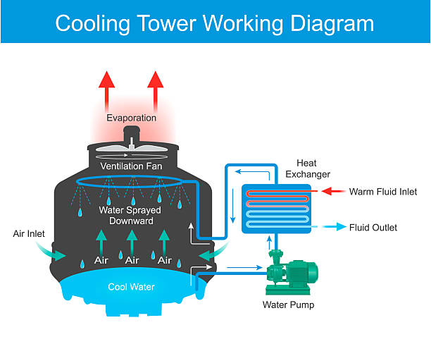
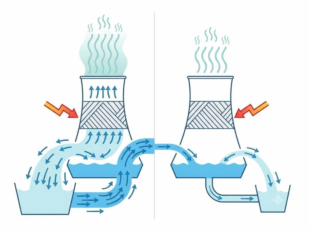
Cooling towers work by evaporation. Warm water flows through the tower, a portion evaporates to release heat, and the rest recirculates. The problem is that only pure water evaporates, every dissolved mineral in that water stays behind. Over time, those minerals build up in the recirculating water, and the concentration keeps rising with every cycle.
COC is simply the ratio that tells you how concentrated the recirculating water has become relative to the original makeup water coming into the system.
A straightforward example: if your makeup water has a total dissolved solids (TDS) level of 200 mg/L, and your recirculating water tests at 800 mg/L, you’re running at COC 4. That means the water in your system is four times as concentrated as the water going in.
That number matters because everything that can go wrong in a cooling tower such as scaling, corrosion, biological fouling gets worse as concentration increases. COC doesn’t cause those problems directly, but it sets the conditions for how severe they become.
Three Methods to Calculate COC for Cooling Tower
There’s more than one way to calculate COC, and which method you use depends on what instrumentation you have available.
Conductivity method is the most common approach in day-to-day operations. Electrical conductivity in water increases as dissolved solids increase, so it works as a reliable proxy for TDS.
COC = Conductivity of recirculating water ÷ Conductivity of makeup water
If your makeup water reads 400 µS/cm and your tower water reads 1,600 µS/cm, you’re at COC 4. This method is easy to automate with a conductivity controller, which is why it’s the standard for ongoing monitoring.
Flow rate method works if you have flow meters installed on both the makeup and blowdown lines.
COC = Makeup water flow rate ÷ Blowdown flow rate
This approach is straightforward but only accurate if drift and evaporation losses are relatively consistent. It’s more useful for checking whether your blowdown rate aligns with your COC target than for real-time control.
Chloride or sulfate ratio method is the most accurate of the three because these ions don’t react with anything in the system, they just concentrate passively. Send water samples from both the makeup and recirculating lines to a lab, and divide the ion concentration in the tower water by the concentration in the makeup water.
COC = Cl⁻ (recirculating) ÷ Cl⁻ (makeup)
This method is worth using when you need to verify COC accurately. For example, when calibrating a new conductivity controller or diagnosing a scaling problem. The US EPA WaterSense program references similar calculation approaches for commercial cooling tower water efficiency benchmarking.
Why Higher COC Saves Water
Raising COC reduces how often you need to discharge water (blowdown) to keep dissolved solids in check, which directly cuts makeup water consumption.
According to the US Department of Energy, increasing COC from 3 to 6 reduces makeup water consumption by around 20% and cuts blowdown volume by roughly 50%. For a large industrial facility running cooling towers continuously, that’s a significant operational saving, both in water costs and in the cost of treating or disposing of blowdown.
The relationship looks roughly like this:
| COC | Makeup water reduction (vs. COC 2) | Blowdown reduction (vs. COC 2) |
| 3 | ~17% | ~33% |
| 4 | ~25% | ~50% |
| 6 | ~33% | ~67% |
| 8 | ~38% | ~75% |
The gains diminish as COC increases, the jump from 3 to 6 saves significantly more than the jump from 6 to 10. And as COC rises, so does the risk of the problems discussed in the next section.
Why COC Has a Ceiling: Four Limiting Factors
Higher COC isn’t always better. There are four factors that set a practical upper limit, and in most systems, at least one of them will constrain how far you can go.
- Calcium hardness and carbonate scaling risk. As calcium and bicarbonate concentrate, the water approaches saturation and calcium carbonate starts to precipitate onto heat exchanger surfaces and tower fill. The Langelier Saturation Index (LSI) is the standard tool for predicting this risk, a positive LSI means the water has scaling tendency, and the higher the COC, the more positive it gets. Scale inhibitors can extend the safe operating range, but they don’t eliminate the constraint entirely. See our guide on cooling tower water treatment chemicals for how scale inhibitors work within a treatment program.
- Silica. Silica has a solubility ceiling of roughly 150 mg/L in most cooling water conditions. Once it exceeds that, it forms hard, glassy deposits that are extremely difficult to remove and largely unresponsive to standard chemical treatment. If your makeup water has elevated silica which is common in regions drawing from groundwater or surface water in parts of Asia, the Middle East, and North Africa, silica concentration often becomes the binding constraint on COC before any other factor does.
- Chloride levels and corrosion risk. Chlorides don’t cause scaling, but at elevated concentrations they become highly corrosive, particularly to stainless steel and copper alloys. The allowable chloride ceiling depends on the materials of construction in your system. Carbon steel systems can generally tolerate higher chloride levels than those using stainless steel components, where stress corrosion cracking becomes a real risk above certain thresholds.
- Discharge regulations. In many jurisdictions, blowdown discharge is regulated for TDS, phosphorus, heavy metals, or specific chemical constituents. Running at higher COC concentrates everything in the blowdown including any treatment chemicals which can push discharge quality outside permitted limits. This is worth checking before setting a COC target, especially in regions with tighter water quality regulations.
How to Determine the Right COC Target for Your System
Given those constraints, arriving at a COC target isn’t a matter of picking a number that sounds reasonable. It requires working through each limiting factor against your actual water chemistry.
The process looks like this:
- Get a full water analysis for your makeup water source: hardness, alkalinity, silica, chlorides, sulfates, TDS, and pH.
- Identify the materials of construction in your system, particularly heat exchangers and pipework.
- Check applicable blowdown discharge limits for your site.
- For each limiting parameter, calculate the maximum COC before that parameter hits its ceiling. Silica and chloride limits are usually straightforward arithmetic; scaling risk requires either an LSI calculation or consultation with your water treatment specialist.
- Take the lowest result across all parameters, that’s your safe operating ceiling.
In practice, most well-treated industrial cooling systems run between COC 4 and 8. Systems on high-quality municipal water with robust chemical treatment programs can sometimes push higher; systems on hard groundwater or with strict discharge requirements often can’t exceed COC 4 or 5 without additional pretreatment on the makeup water side.
How to Control COC in Practice
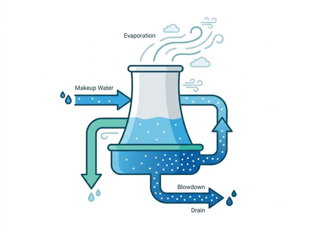
COC doesn’t manage itself. The way you control it is through blowdown — deliberately discharging a portion of the concentrated recirculating water and replacing it with fresh makeup water. The more frequently you blowdown, the lower the COC; the less you blowdown, the higher it climbs.
Manual blowdown opening a valve on a fixed schedule is common in smaller systems but inherently imprecise. It doesn’t account for changes in evaporation rate, makeup water quality, or seasonal conditions, which means you’re either over-bleeding and wasting water, or under-bleeding and drifting above your target COC.
A conductivity controller automates this by continuously measuring the tower water conductivity and triggering blowdown only when it exceeds the set point corresponding to your target COC. If your makeup water has a conductivity of 400 µS/cm and your target is COC 5, you’d set the controller to bleed when tower conductivity hits 2,000 µS/cm. This is more accurate, more water-efficient, and easier to document for compliance purposes. The ASHRAE cooling tower water management guidelines recommend automated conductivity-based blowdown control as part of a well-managed water program.
COC and Your Chemical Treatment Program
COC and chemical dosing are directly connected, and adjusting one without reconsidering the other is a common mistake. When you raise COC, you’re concentrating not just minerals but also any treatment chemicals in the system. Scale and corrosion inhibitors that were dosed for COC 4 may not be sufficient at COC 6 if the mineral load has increased proportionally.
At the same time, biocide efficacy can be affected by higher TDS environments, and pH tends to become harder to stabilize as alkalinity concentrates. Any time you change your COC target, upward or downward, your chemical treatment program should be reviewed alongside it, not separately.
Common COC Mistakes and What They Cost
Running COC too low is often treated as the safe option, but it wastes water and inflates blowdown disposal costs. For facilities that pay sewer connection fees or have high makeup water costs, this adds up quickly.
Running COC too high without adjusting the treatment program is the more damaging scenario. Scale buildup on heat exchangers is gradual and doesn’t trigger alarms — it just quietly reduces heat transfer efficiency, which shows up as higher energy consumption before it eventually causes a blockage or equipment failure.
Relying only on conductivity and ignoring individual ions is a less obvious but real problem. Conductivity measures total dissolved solids collectively. If silica or chloride concentrations are climbing toward their limits while overall conductivity looks normal, you won’t catch it without ion-specific testing. Periodic lab analysis of the recirculating water not just conductivity checks is the only way to know whether individual parameters are within safe limits.
If you’re looking to optimize your COC targets or evaluate whether your current blowdown control setup is working effectively, contact our engineering team for a system review.